"MICROBUSA"
15th march
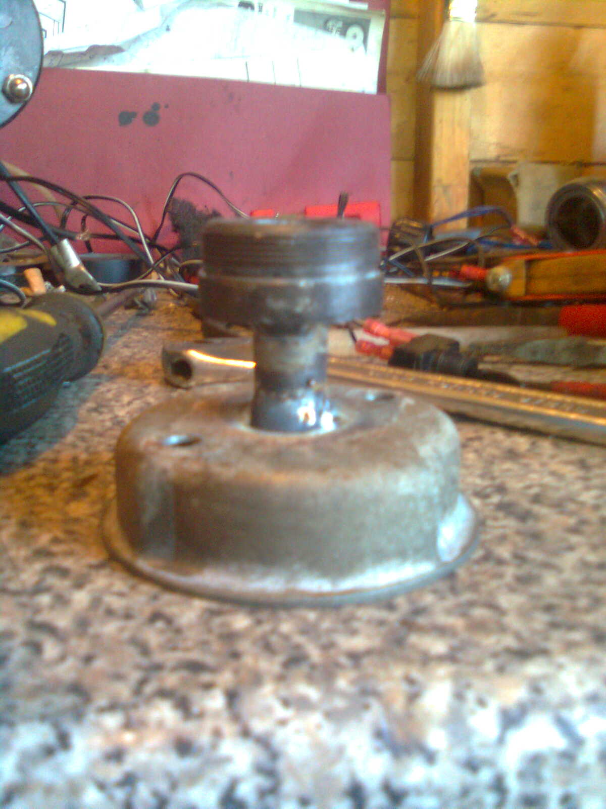
One concern I had was “run out” would there be any vibration?
I was very surprised to find out there was only 0.020” of run out, minimal vibration and nothing to worry about.
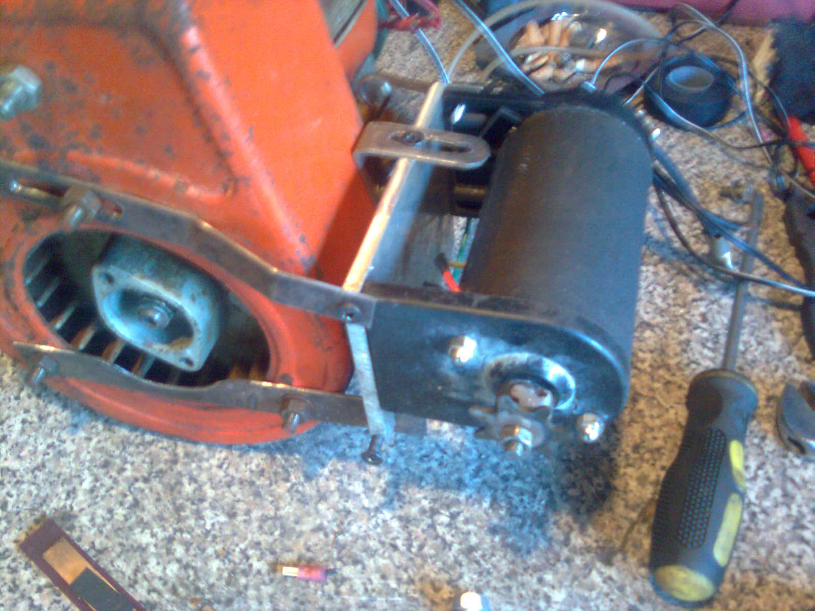
The drive cog from the end of the colts clutch drum was drilled out to fit the shaft on the 12v motor then drilled thru the cog inline with the hole in the motor shaft and drove a roll pin thru the hole and tightened the nut to lock into place.
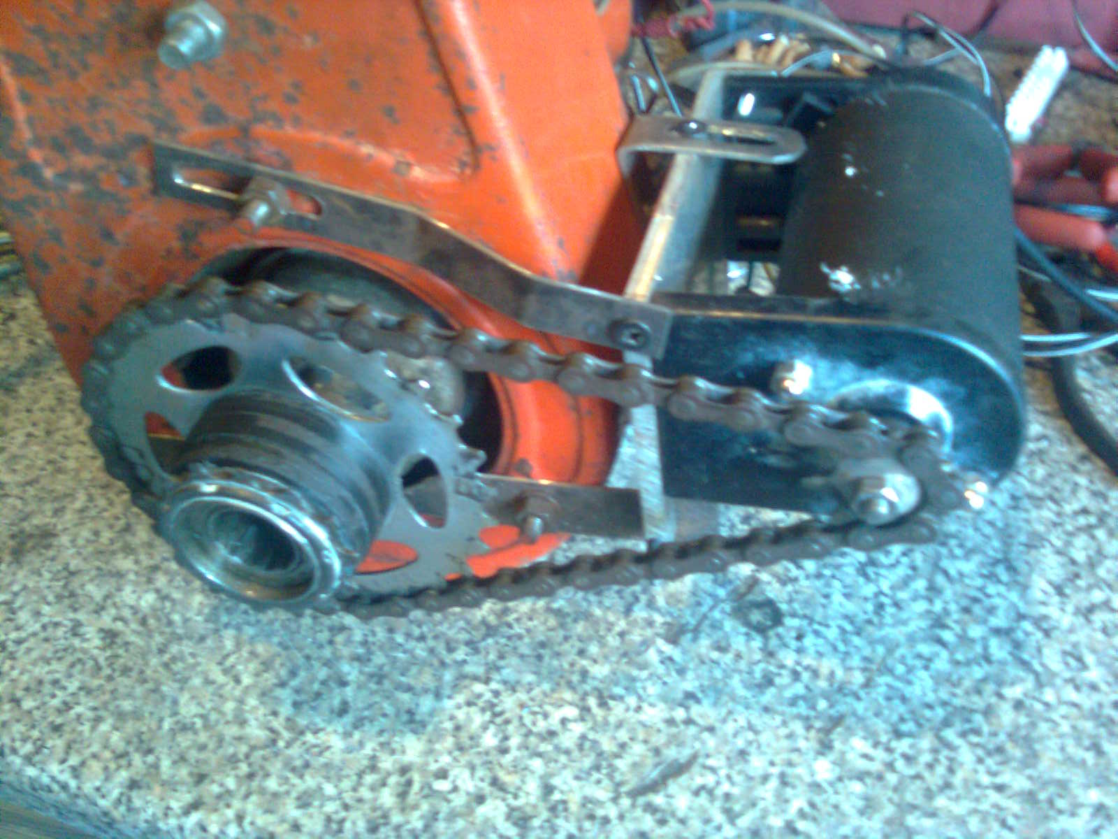
Also I had removed the stator and fitted a switched circuit onto the low tension side of the coil to be able to shut off the engine by the ignition switch.
23rd March
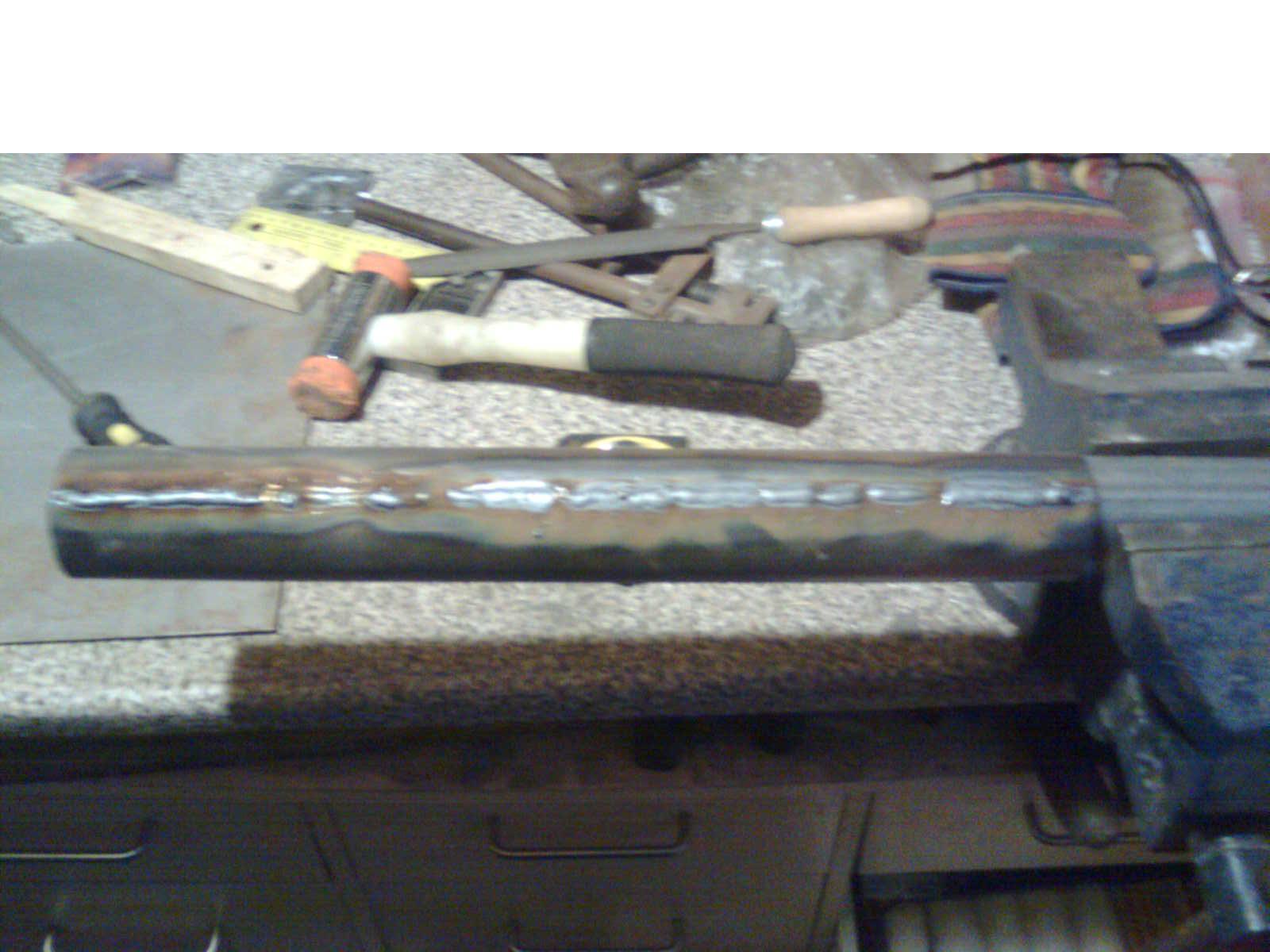
Then welded the seam.
Two circular discs were cut for each end, one with a round hole and the other with a square hole
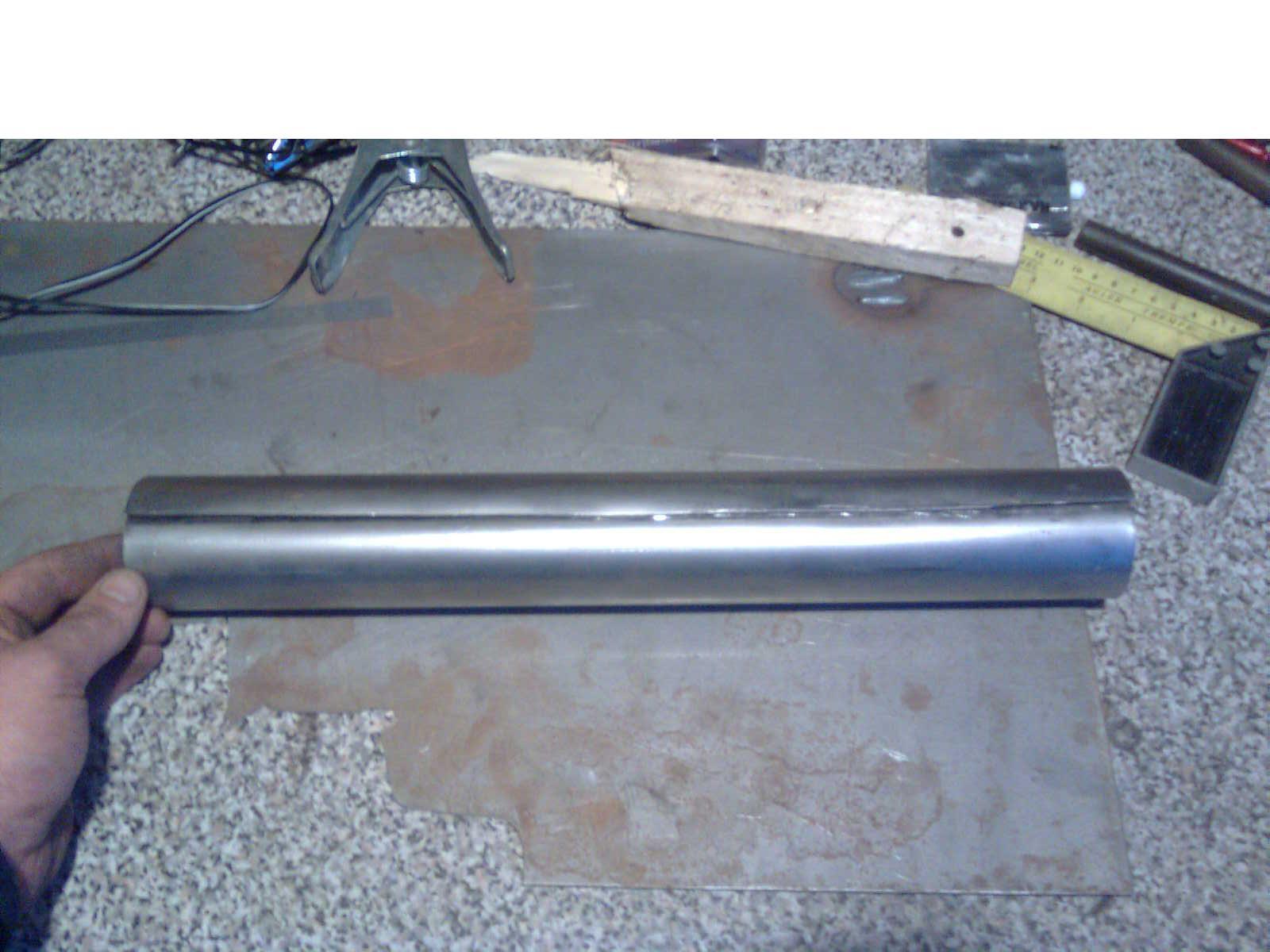
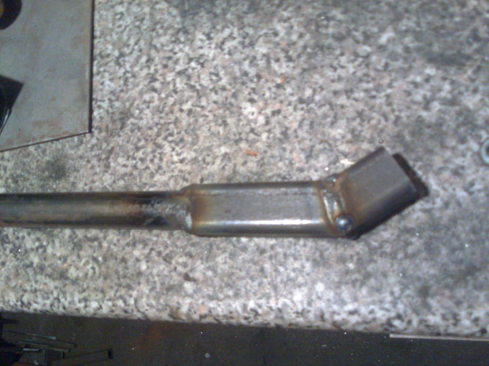
A piece of ¾” square tube was used to make the tailpipe I cut a v out of one side bent it round and welded the joint and a piece of 20mm tube was used for the straight section.
On the straight pipe I cut slits into it and inserted a flat screwdriver and twisted it so they would act like a scoop and deflect some of the gases out of the tube into the larger tube of the muffler.
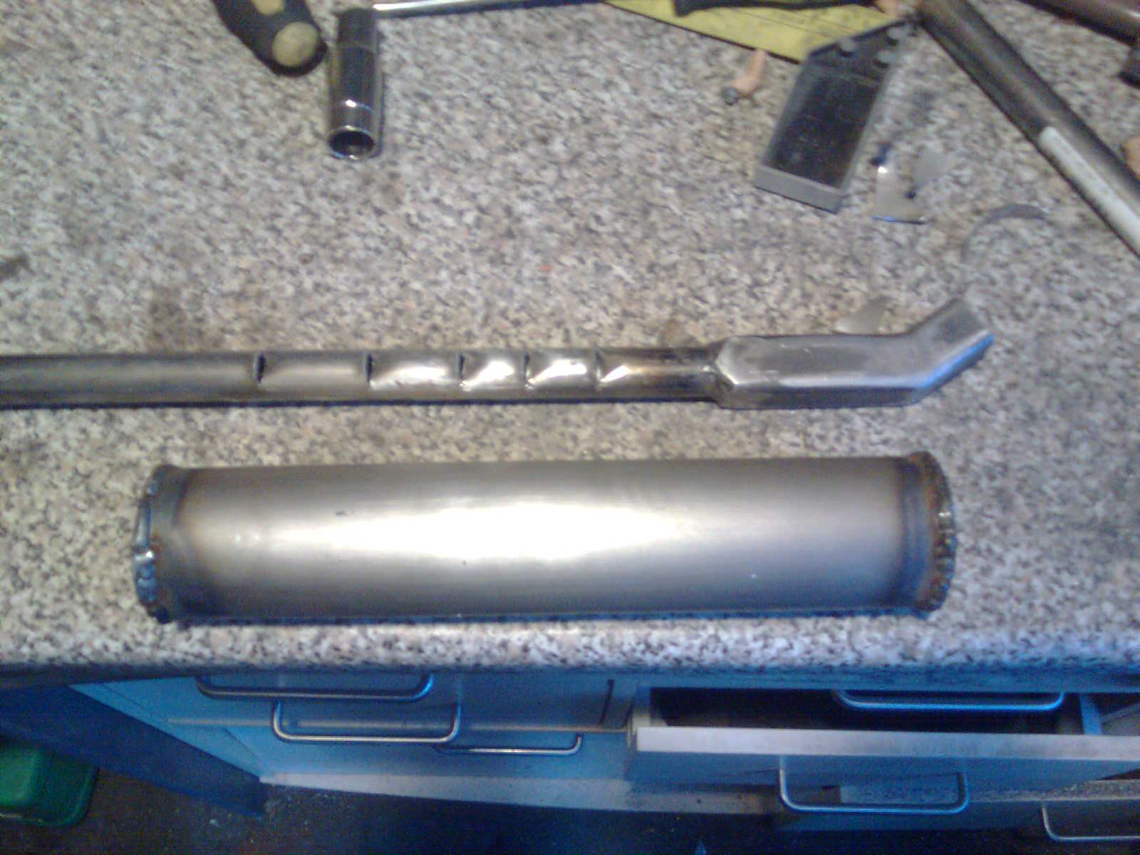
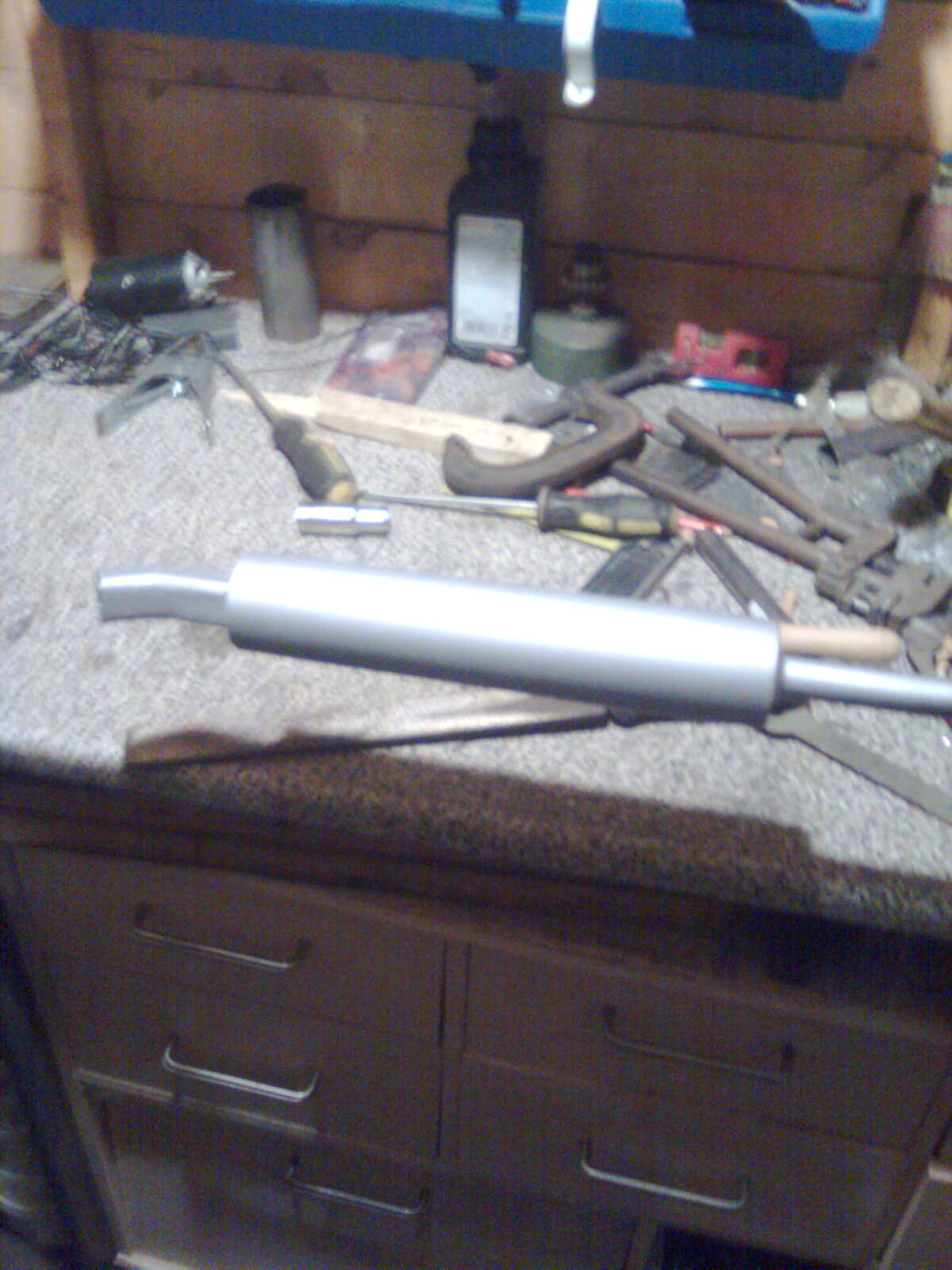
Then assembled all the parts and checked for leaks (put my hand over one end and blew down the other lol) now leaks that I could tell of. Finaly a coat of silver paint.
29th March 2009
Today i decided i was going to do the steering rack and the linkages.
I am going to use the escort steering column just needto make a few mods to fit and work. The top mounting bracket was removed from the column and a small bracket was made and welded to the colomn and the round bar on the top of the chassis, the other end of the column was attached to an upright 3/4" tube wich was attached to the chassis.
the steering rack itself was wade from 8mm square section sliding inside two 10mm square section guides wich were welded ontop of two pieces of 3/4" section at the front of the chassis leaning inwards.
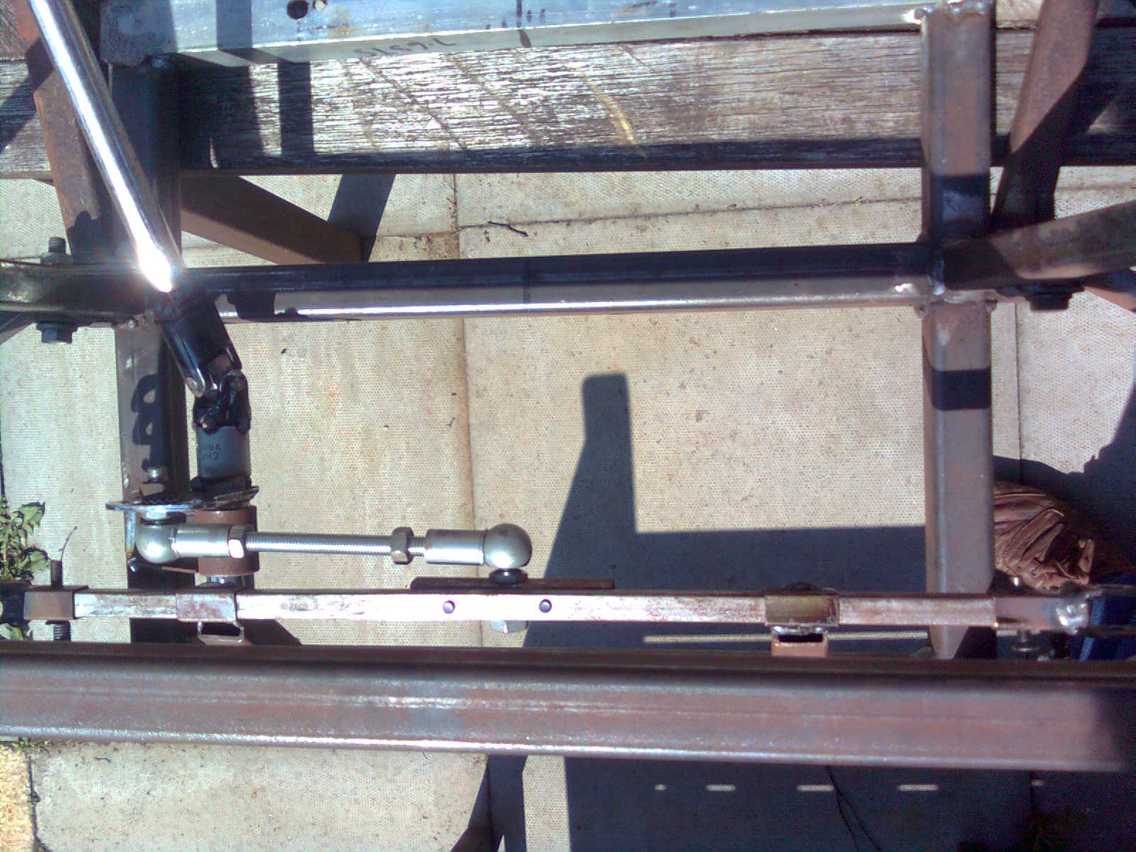
The last six inches was cut off the bottom of the column and filed into a square at the end so it would fit into a 1/2" socket universal joint.
A 10" socket extension bar was fitted then another universal joint.
All welded together for strength.
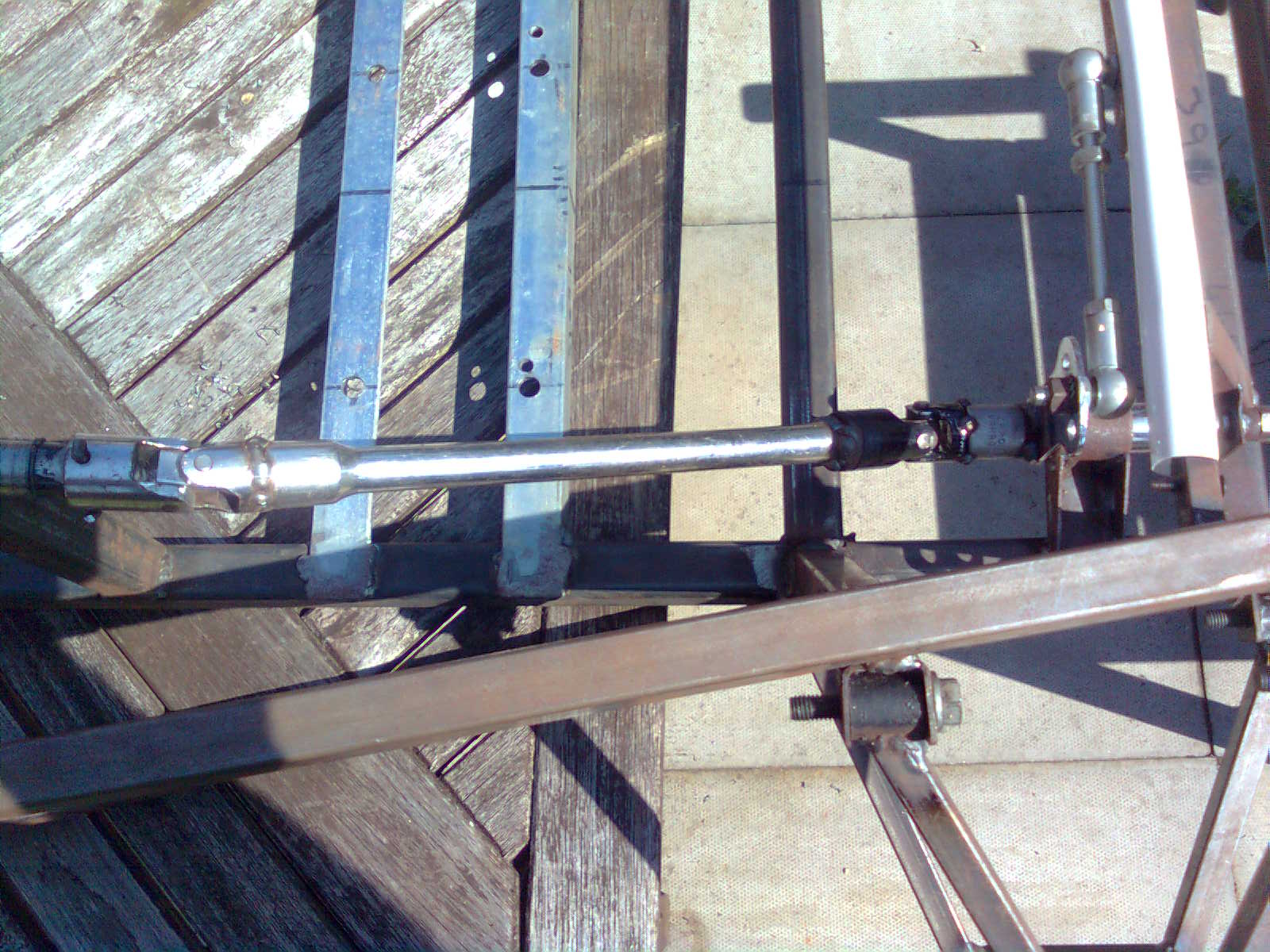
I used a kart steering column (£8.99 secong hand from ebay with link arms) cut down to just the end section and a 3" socket extension bar hammered inside it and welded together for extra strength.
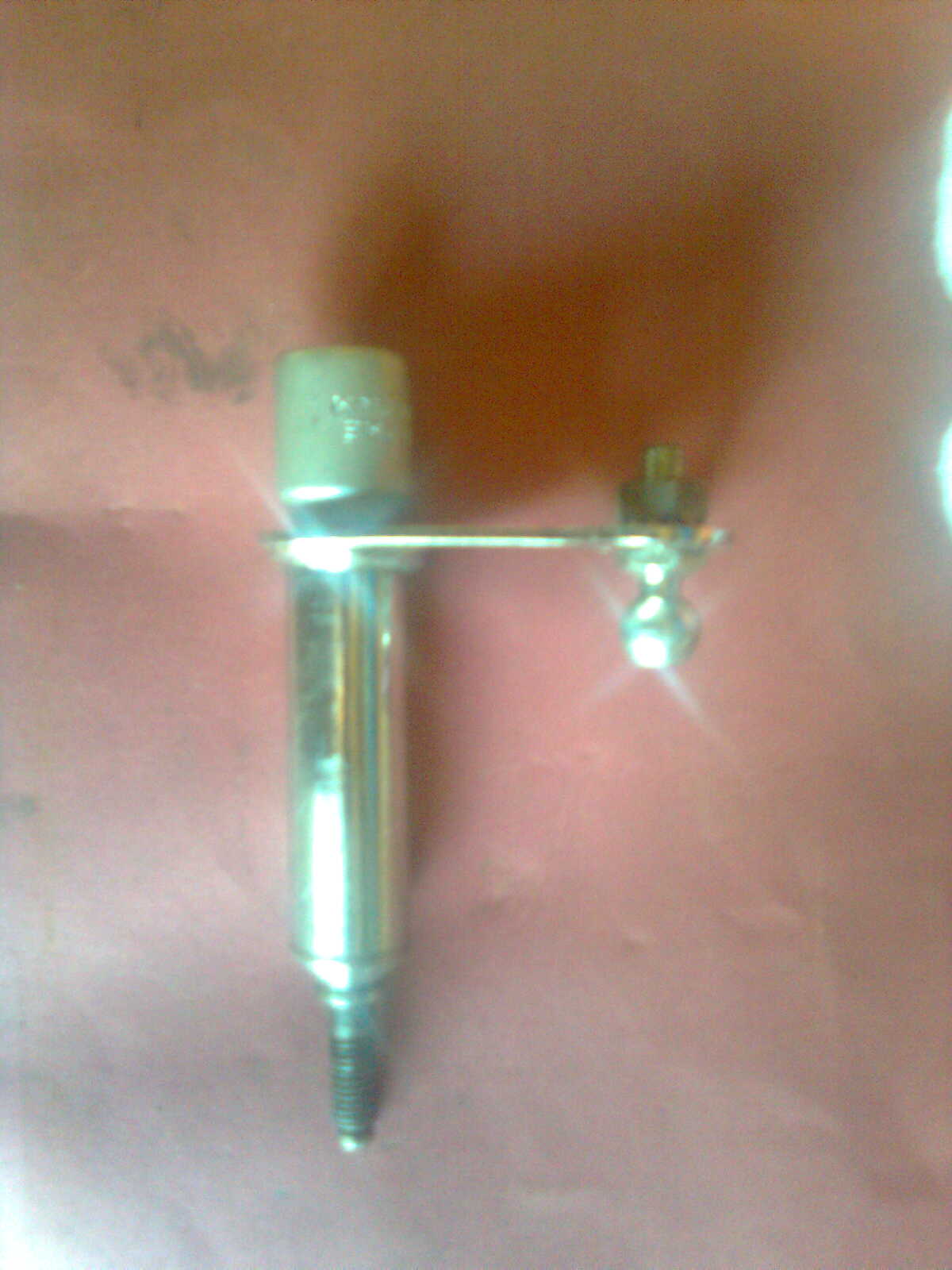
This part was then fitted to the chassis at the lower most forward part by a bracket with a hole in wich the threaded part was inserted and a nylock nut to secure.
This single point was not strong enough to hold the steering firm.
this was overcome by another bracket.with a copper liner/bush.
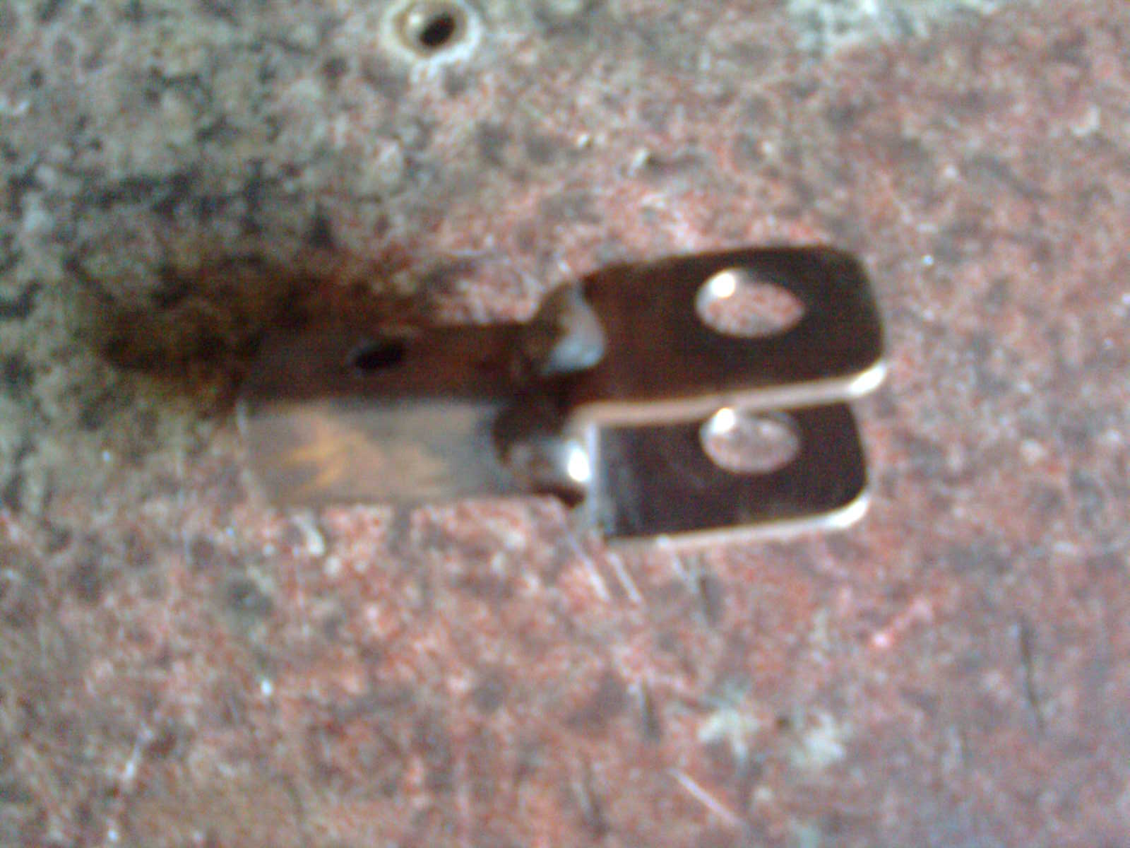
here are the bracket components i made from 1.5mm steel plate.
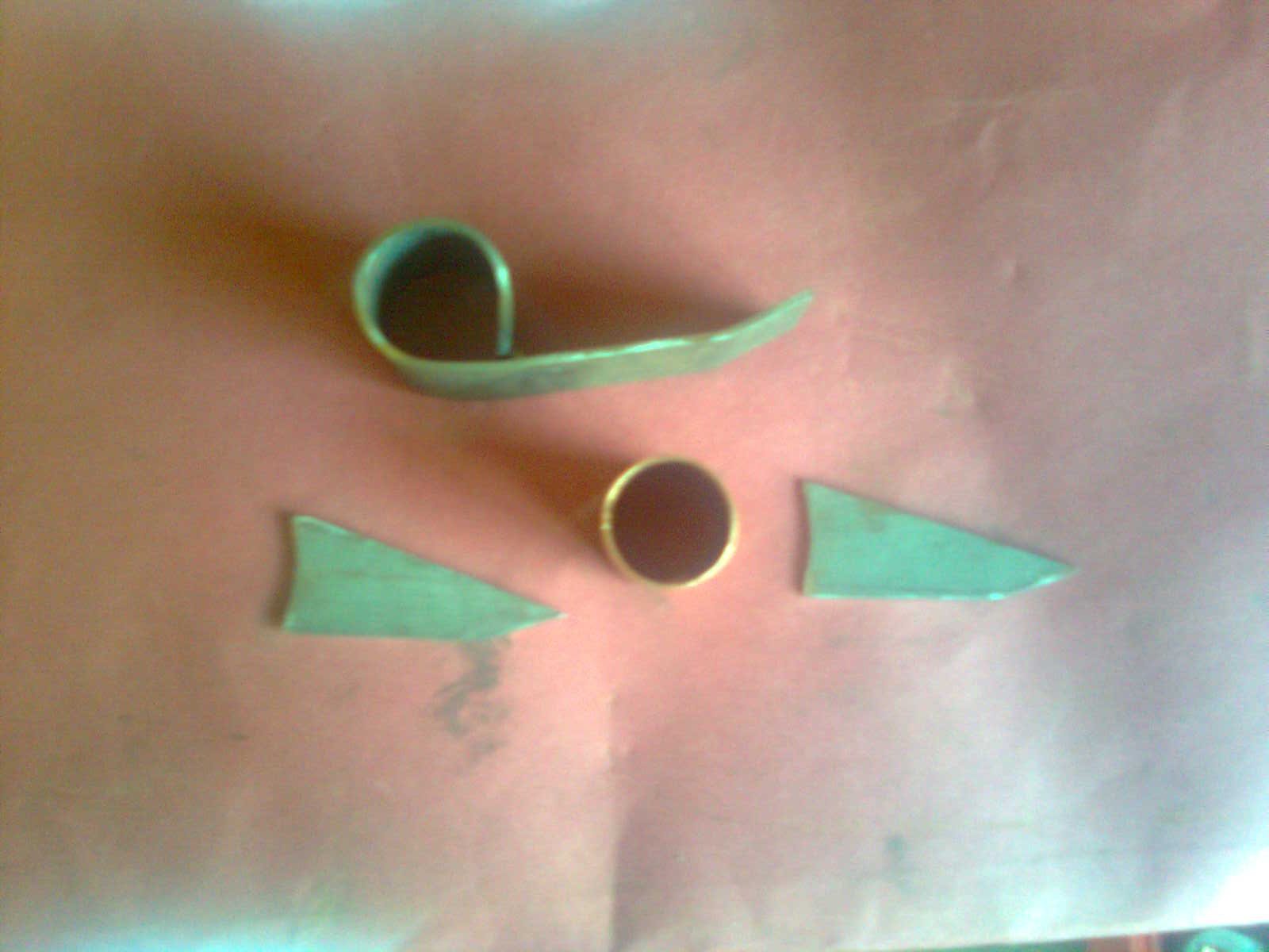
These were welded together, the copper bush was 22mm coper tubeing perfect tight slide fit this was slid over the lower steering joint and then the bracket was welded onto the chassis.
To connect the the link arms to the rack i made two of these....
using 10mm square section and a fabricated "U" shaped bracket to conect to the tiebars.